Concrete
Scanning
High-resolution GPR imaging — locating rebar, post-tension cables, conduits, voids and delamination in slabs, bridges, columns and jetties before you cut, core or load.
Non-Destructive
Sub-Surface Investigation
Concrete scanning uses high-frequency ground penetrating radar (GPR) to image the internal structure of concrete elements — locating reinforcement, post-tension cables, conduits, voids and delamination without drilling, coring or disrupting the structure.
Spaulding Geophysics operates antenna frequencies from 1600 MHz — suited to deep footings, thick slabs and heavier reinforcement — through to 2700 MHz for shallow, high-resolution work where fine rebar spacing, cover depth accuracy and surface-layer defect characterisation are the priority. Antenna selection is determined by the investigation objective prior to mobilisation.
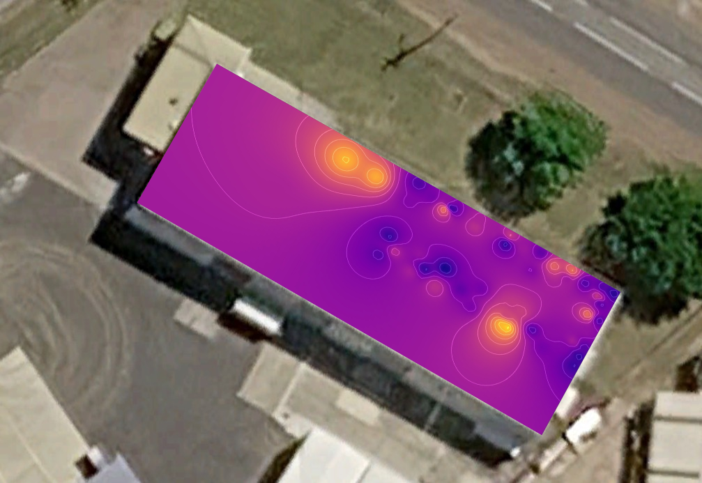
Survey outputs range from single-line 2D B-scan profiles for targeted investigations, to full 3D C-scan volumes assembled from gridded profiles — enabling plan-view mapping of rebar grids, tendon layouts and defect extents at any depth slice. Processed data is delivered as georeferenced CAD overlays, marked site drawings and formal PDF reports, providing engineering teams with unambiguous, actionable subsurface information.
Frequency Selection
for Depth & Resolution
Antenna frequency governs the fundamental trade-off between resolution and penetration depth. Higher frequencies resolve finer features at shallower depths; lower frequencies sacrifice resolution to image deeper targets. Spaulding Geophysics selects antenna frequency based on the target type, expected depth and structural element being investigated.
For most slab and column scanning programs, the 2300 MHz antenna provides the optimal balance — resolving individual rebar bars, post-tension ducts and conduits to depths up to 300–400 mm. Where cover depth measurement accuracy, delamination detection in thin sections, or tightly-spaced shallow rebar is the objective, the 2700 MHz antenna is deployed for its finer spatial resolution. Deep footings, thickening beams and secondary rebar layers require the low 1600MHz antenna to accurately resolve features.
| Antenna | Frequency | Typical Depth | Best For |
|---|---|---|---|
| High Resolution | 2700 MHz | 0–250 mm | Shallow rebar, cover depth, thin slabs, surface delamination |
| Standard Concrete | 2300 MHz | 0–400 mm | Rebar mapping, PT cables, & conduits |
| Deep Footings | 1600 MHz | 0–1200 mm | Deep footings & thickening beams & secondary rebar sections |
Depth estimates assume typical concrete dielectric properties. Depth range is reduced in saturated, carbonated or high-chloride concrete. Spaulding Geophysics advises on expected performance prior to mobilisation.
What We
Scan
GPR concrete scanning is applicable to any reinforced or prestressed concrete element. Spaulding Geophysics regularly investigates the following structure types across Tasmania and Victoria.
2D Profiling &
3D Volume Scanning
Spaulding Geophysics delivers both 2D and 3D GPR survey outputs depending on investigation objectives, site access and the complexity of the subsurface target environment.
When to Commission
Concrete Scanning
Concrete scanning is warranted wherever sub-surface knowledge is required before or after any intrusive or load-affecting work — or when a structure's internal condition is in doubt.
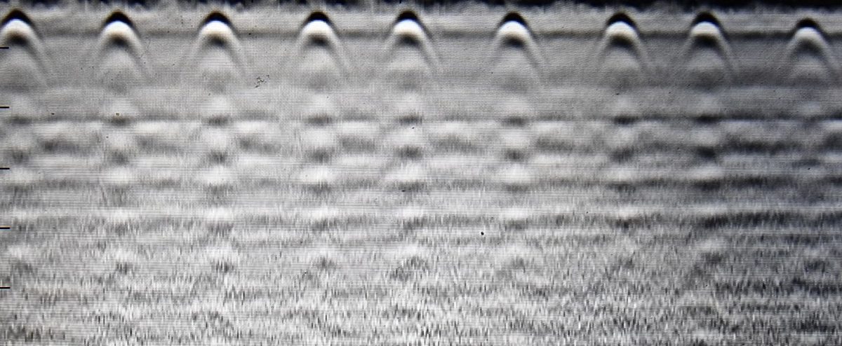
B-scan radargram showing hyperbolic diffraction signatures characteristic of rebar mesh — each hyperbola apex corresponds to a bar intersection; depth is derived from hyperbola geometry and concrete velocity calibration
From Raw Signal
to Actionable Output
All GPR data is processed through a structured conditioning workflow before spatial assembly and interpretation. Signal processing removes acquisition artefacts and enhances target responses; spatial assembly transforms line profiles into georeferenced plan products.
- Time-zero correction — aligns the air–ground interface to t=0 across all traces
- DC dewow — removes low-frequency drift introduced by inductive coupling
- Bandpass filter — suppresses noise outside the antenna frequency band
- Gain application — SEC or manual gain restores amplitude with depth
- Background removal — subtracts horizontal banding from antenna ringing
- Migration — collapses hyperbolic diffractions to point targets and corrects for wave divergence
Clear, Georeferenced
Reporting
Spaulding Geophysics delivers all findings in a format suitable for direct use by structural engineers, project managers and drilling or cutting crews — whether that is a marked slab on the day, or a formal engineering report.
| Deliverable | Detail |
|---|---|
| Site markings | Rebar, PT cable and conduit positions stencilled directly onto the slab surface for safe cutting or coring (where requested) |
| B-scan radargrams | Processed cross-section profiles for all scan lines, annotated with interpreted target depths |
| C-scan depth slices | Plan-view amplitude maps at user-defined depths — revealing rebar grid geometry and defect extents (3D surveys) |
| CAD overlay | Georeferenced DXF file mapping rebar, tendons, conduits and anomalies onto the provided site plan |
| Cover depth table | Measured reinforcement depths at each interpreted target — reported by grid reference |
| Defect mapping | Void, delamination and honeycombing extents mapped in plan and cross-section with severity classification |
| PDF report | Formal written report with methodology, results, interpretation and recommendations — suitable for engineering and regulatory submissions |