Seismic
Surveys
MASW · P-Wave Refraction · VS30 · Bedrock Mapping
Applications
Analysis of Seismic Waves
Seismic methods measure and analyse the characteristics of acoustics waves to understand the structure and elastic properties of rocks and soils.
VS30 — Average Shear Wave Velocity to 30 metres depth. The preferred input for site sub-soil classification under AS 1170.4.
MASW
Multi-Channel Analysis of Surface Waves
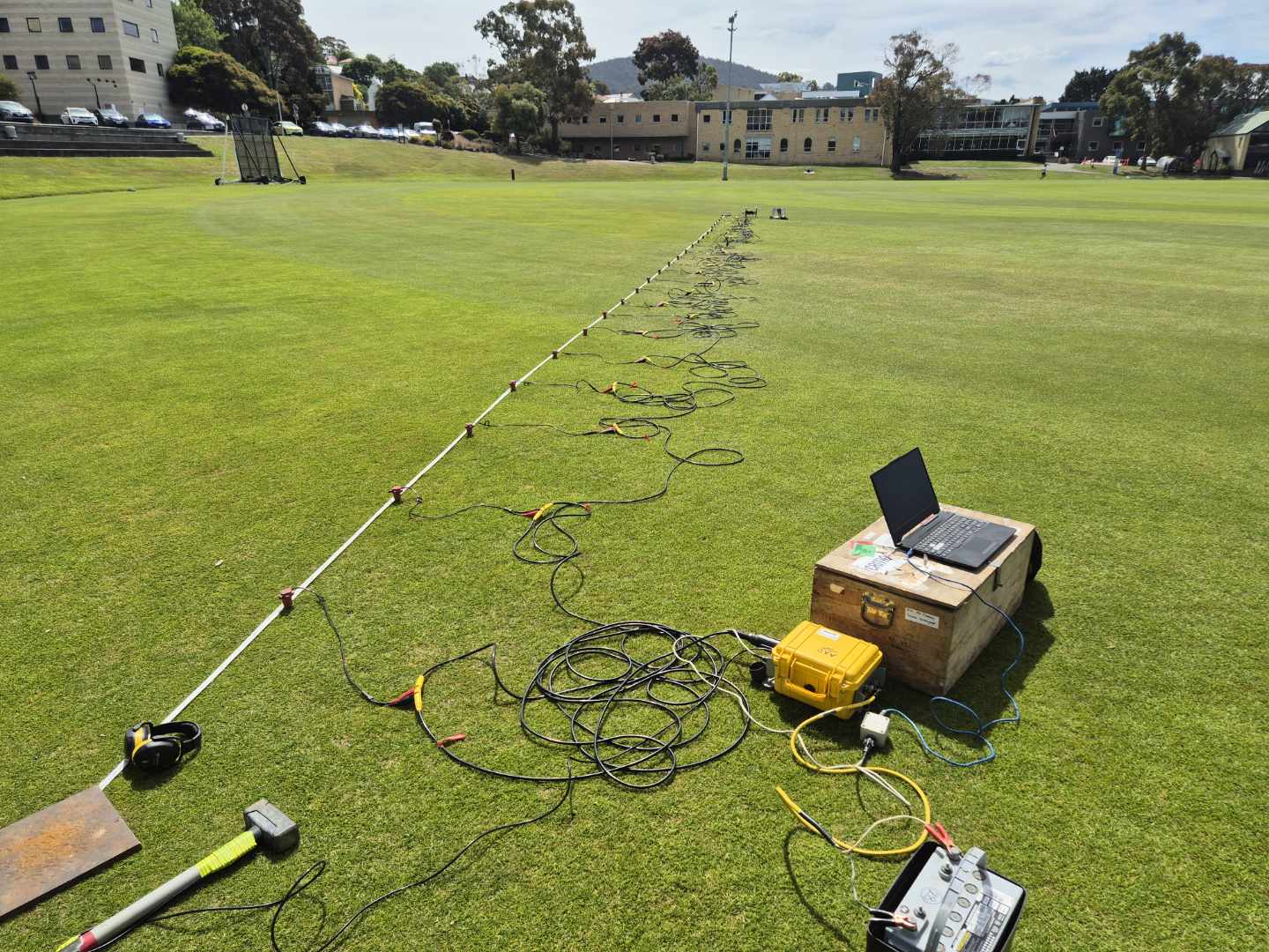
MASW is a seismic technique that records surface waves generated by sources such as a sledge hammer and evaluates their propagation behaviour to determine shear-wave velocity (Vs) variations beneath the ground.
Shear-wave velocity is closely linked to key elastic properties, including Young's and shear moduli, making it a direct measure of ground stiffness and load-bearing capacity.
VS30 — Average Shear Wave Velocity to 30 metres depth. The preferred input for site sub-soil classification under AS 1170.4.
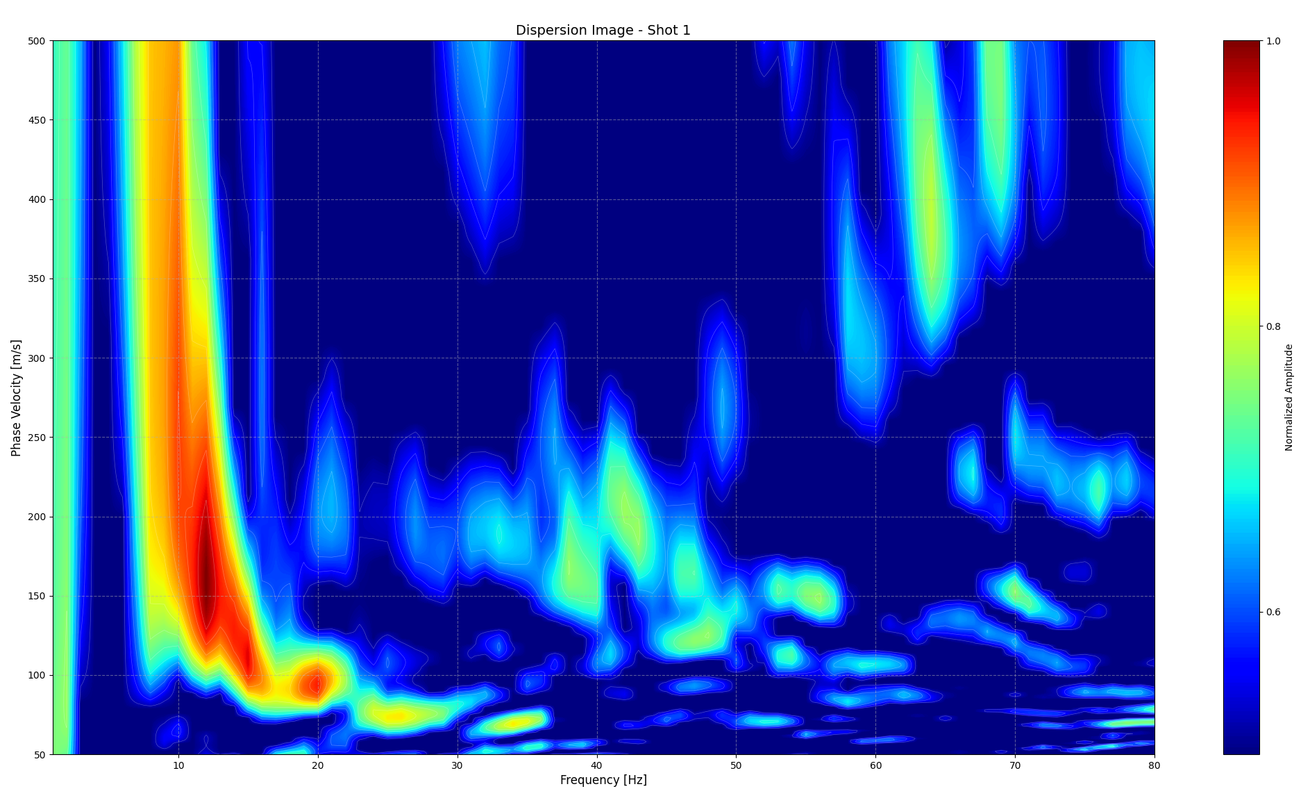
Dispersion Image — Phase Velocity (m/s) vs Frequency (Hz)
P-Wave
Seismic Refraction
Seismic wave analysis provides engineers not only with subsurface lithological information but also with dynamic ground properties essential for accurately estimating modulus parameters and evaluating load-bearing capacity.
- Profiling depth to bedrock and delineating weathered zones
- Defining lithology and stratigraphic sequences
- Determining Young's modulus, Poisson's ratio, shear and bulk modulus
- VS and VS30 as direct indicators of ground stiffness
- Identifying voids, sinkholes, and areas of ground subsidence
Site Sub-Soil
Classification
Under the National Construction Code, earthquake design follows AS 1170.4, requiring assignment of a site sub-soil class (Ae to Ee) based on seismic response.
MASW provides a non-intrusive means of measuring Vs profiles and deriving VS30, enabling engineers to objectively classify ground conditions and quantify amplification potential.
These site classes directly influence the design earthquake forces applied to structural and non-structural elements of any building.
| Class | Determination | VS30 (m/s) | |
|---|---|---|---|
| Ae | Strong Rock | > 1500 | ✓✓✓✓✓ |
| Be | Rock | > 360 | ✓✓✓✓ |
| Ce | Shallow soil | N/A* (site period ≤ 0.6 s) |
✓✓✓ |
| De | Deep / Soft Soil | N/A* (site period > 0.6 s) |
✓✓ |
| Ee | Very Soft Soil | ≤ 150 (soft layers > 10 m) |
✓ |
*For Classes Ce and De, the preferred method (per AS 1170.4) is the low-amplitude natural site period calculated from your full MASW Vs profile. VS30 is still derived and used as supporting data.
Concentrated Load
on Ultra-Stable Ground
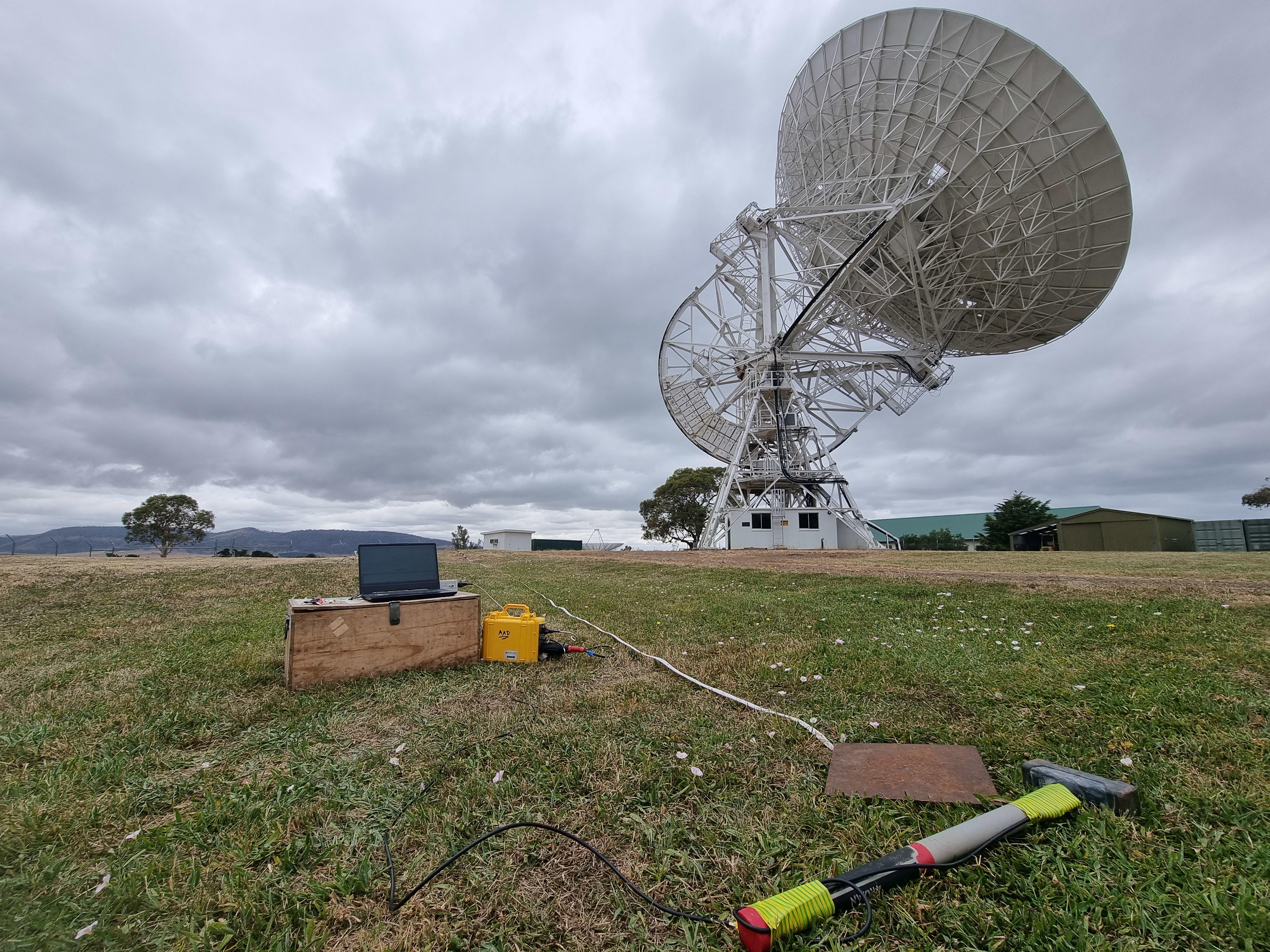
The Mount Pleasant Radio Telescope (26 m steerable dish) presents unique conditions that demand exceptional foundation performance. The massive structure and its supporting pedestal concentrate enormous weight on a relatively small footprint — typically in the order of ~10 m across — while the dish must maintain sub-millimetre pointing accuracy under continuous dynamic loads from precision tracking motors, wind forces, and operational movements.
Because radio-astronomy observations are extremely sensitive to even tiny vibrations, knowledge of the ground’s dynamic properties obtained through seismic surveys is critical. Static borehole parameters alone are insufficient — elastic moduli derived from shear-wave velocity are required to model soil–structure interaction, foundation stiffness, and vibration transmission under cyclic excitation and low-level seismic events.
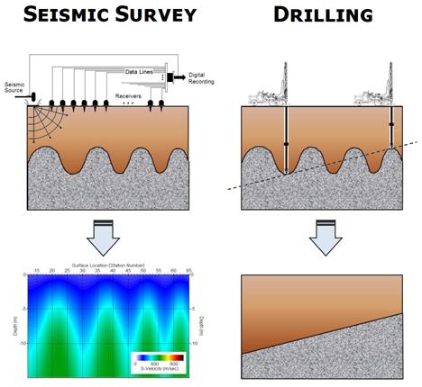
MASW surveys deliver shear-wave velocity (Vs) profiles and VS30 values that directly satisfy the geotechnical reporting requirements for high-precision astronomical facilities in Australia, providing site-specific data that cannot be reliably inferred from drilling alone.
Precision tracking motors and wind-induced forces generate cyclic loads that stress the soil–foundation interface at frequencies the ground responds to dynamically. Radio telescopes demand vibration levels orders of magnitude lower than conventional structures — a regime that static bearing capacity calculations cannot address.
From Survey to
Foundation Parameters
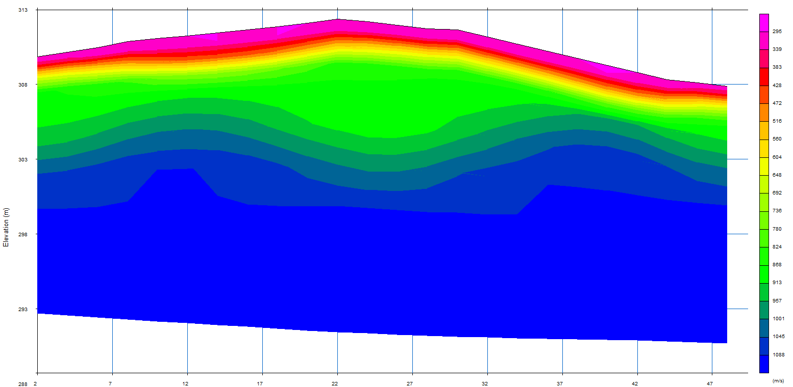
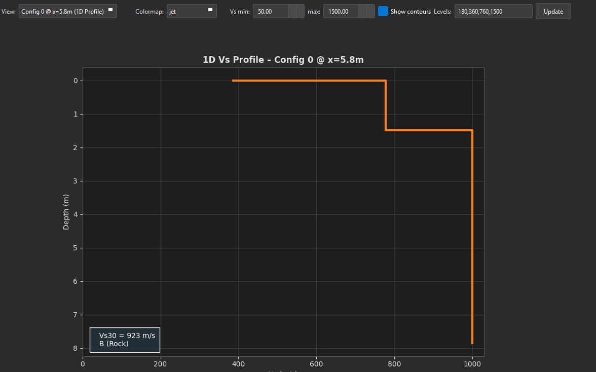
MASW delivers two complementary outputs that directly feed foundation design — a depth-resolved shear-wave velocity profile and the Vs30 site classification parameter required under AS 1170.4.
Dynamic Ground
Parameters for Design
Areas We
Serve in Tasmania
Spaulding Geophysics provides comprehensive seismic refraction, MASW and reflection surveys across Tasmania, from Hobart and Launceston to regional centres, coastal towns, and remote communities statewide.
Spaulding Geophysics delivers comprehensive seismic refraction, MASW and reflection surveys across all of Tasmania — including Hobart, Launceston, Devonport, Burnie, Ulverstone, George Town, Longford, Deloraine, Smithton, Wynyard, Bicheno, St Helens, Scottsdale, Queenstown, Huonville, Kingston, Kettering, Bruny Island and surrounding communities. Remote and regional sites welcomed.