Resistivity
& IP
ERI · Induced Polarisation · 2D / 3D Inversion · Chargeability
Resistivity &
Induced Polarisation
Electrical Resistivity Imaging (ERI) and Induced Polarisation (IP) are active-source geophysical methods that image subsurface electrical properties by injecting direct current (DC) into the ground via steel electrodes and measuring the resulting voltage distribution at the surface.
Apparent resistivity (ρa) is computed from the current (I) and voltage (V) readings together with a geometric factor (K) determined by electrode spacing. Multi-electrode arrays deployed along a profile allow 2D or 3D inversion of subsurface resistivity structure. The IP effect — measured as chargeability or phase shift — captures the ability of earth materials to store and release electrical charge, providing a complementary dataset to resistivity alone.
ERT/IP resolves lithological contacts, groundwater horizons, contamination plumes and mineralised zones at depths from centimetres to hundreds of metres — all without drilling.
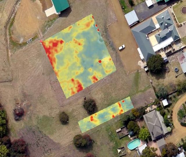
Apparent resistivity (ρₐ) tomographic depth-slice at archaeological site
Raw pseudosections are not true depth sections — the apparent resistivity is a weighted average of all material sensed by each measurement. Least-squares inversion (RES2DINV / E4D) iteratively updates a subsurface resistivity model until the forward-modelled response matches observed data within a defined misfit, producing a calibrated true-resistivity cross-section.
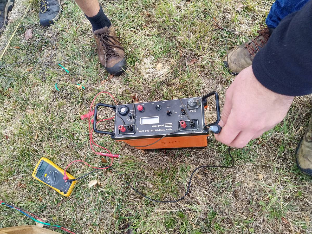
ERI / IP System
Operation
Multi-channel resistivity systems deploy up to 256 electrodes in a single spread, enabling rapid automated roll-along acquisition for deep 2D sections or dense 3D grid surveys. IP chargeability is recorded simultaneously at no additional field cost.