Ground Penetrating Radar
Tasmania
High-resolution subsurface imaging from the surface — utilities, voids, pavement layers, archaeological features and more.
Ground-Penetrating Radar (GPR)
Tasmania
Ground-Penetrating Radar (GPR) surveys across Tasmania for underground utilities, voids, buried structures, concrete, pavements, archaeological features and subsurface investigations. Spaulding Geophysics provides high-resolution GPR surveys in Hobart, Launceston and regional Tasmania using a range of antenna frequencies selected to match the target depth, ground conditions and required resolution.
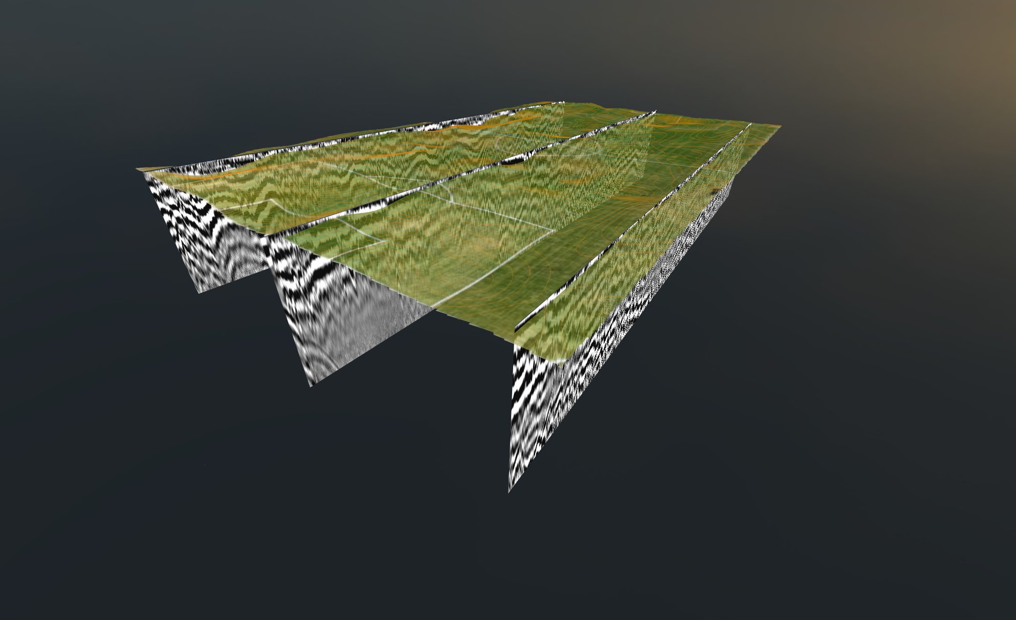
Our GPR surveys can be undertaken as targeted profiles, systematic grids or high-density 2D and 3D investigations. Data can be processed into radargrams, depth slices, interpreted horizons, 3D subsurface surfaces and georeferenced maps, providing practical outputs for engineering, construction, utility locating, heritage, archaeology and environmental investigations.
Spaulding Geophysics operates a broad range of GPR antenna frequencies from 100MHz to 2700MHz, allowing the survey configuration to be selected according to the investigation objective. Higher-frequency antennas provide greater resolution for shallow targets, while lower-frequency systems provide greater penetration for deeper investigations.

What GPR
Is Used For
GPR is one of the most versatile near-surface geophysical methods — applicable wherever a dielectric contrast exists between a target and its host material. Antenna frequency and survey geometry are tailored to each application.
Dielectric Properties
& Wave Velocity
The velocity of a GPR wave through a material is governed by its relative dielectric permittivity (εᵣ) — a dimensionless measure of how easily a material is polarised by an electromagnetic field. Water has an exceptionally high permittivity (~80), making moisture content the dominant control on GPR velocity in most soils and rocks.
Depth estimation requires knowledge of the wave velocity in the material being imaged. Velocity is derived from hyperbolic diffraction fitting in the radargram, or applied from test pit samples at designated locations.
The velocity relationship is:
v = c / √εᵣ → depth = v × t / 2
where c = speed of light (0.3 m/ns) and t = two-way travel time. Accurate velocity determination is critical — a 10% velocity error produces a 10% depth error.
| Material | εᵣ | Velocity (m/ns) | Attenuation |
|---|---|---|---|
| Air | 1 | 0.30 | None |
| Ice | 3–4 | 0.16 | Very Low |
| Dry Sand | 3–5 | 0.15 | Low |
| Granite / Limestone | 4–8 | 0.13 | Low |
| Asphalt (dry) | 3–5 | 0.15 | Low |
| Concrete | 6–11 | 0.11 | Low–Med |
| Dry Soil / Loam | 4–6 | 0.13 | Low–Med |
| Moist Soil | 10–20 | 0.09 | Moderate |
| Wet Sand / Gravel | 20–30 | 0.06 | Moderate |
| Saturated Clay | 25–40 | 0.05 | High |
| Seawater | ~80 | 0.033 | Very High |
| Fresh Water | ~80 | 0.033 | Moderate |
GPR
Workflow
Spaulding Geophysics processes all GPR data using a range of software appropriate for the data processing needs albeit the premium software GEOLITIX ensures full compatibility with multichannel acquisition formats and access to the complete processing chain.
All GPR datasets are processed through a structured sequential workflow before spatial assembly and interpretation. Raw traces are conditioned to remove acquisition artefacts, then assembled into georeferenced volumes from which mapped deliverables are extracted.
- Time-zero correction — aligns the air–ground interface to t=0 across all traces
- DC dewow — removes low-frequency drift introduced by inductive coupling
- Bandpass filter — suppresses noise outside the antenna frequency band
- Gain application — SEC or manual gain restores amplitude with depth
- Background removal — subtracts horizontal banding from antenna ringing
- Migration — collapses hyperbolic diffractions to point targets and corrects dip
- Topographic correction — applies GPS elevation data to produce true-depth sections
- 3D volume assembly — all profiles and channels assembled into a georeferenced data volume
- Depth-slice generation — horizontal time/depth slices reveal plan-view target geometry
- Horizon picking — semi-automatic reflector tracking across parallel profile grids
- Surface interpolation — picked horizons interpolated to continuous 3D depth surfaces
- Utility mapping — hyperbola centres extracted and mapped as georeferenced utility lines
- Topographic drape — surfaces draped on DTM for true 3D visualisation
- Export — outputs to DXF, SHP, GeoTIFF, CSV and PDF report formats